1成果简介
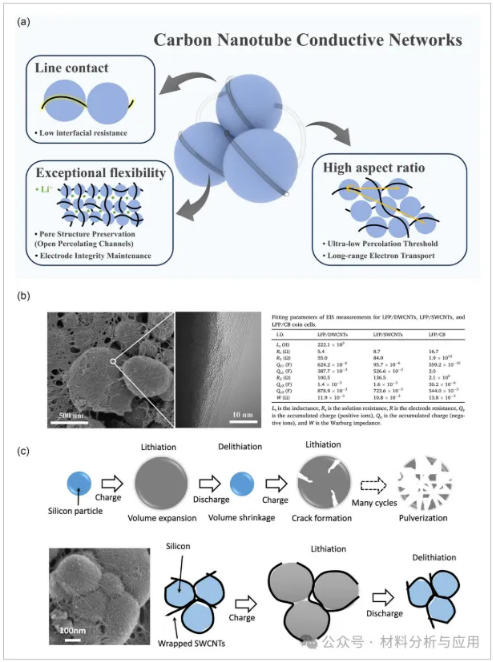
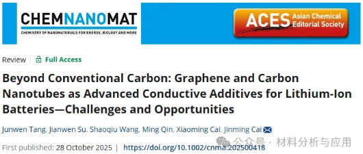
图2、a) CNT conductive network and its characteristic advantages. b) SEM image of CNT conductive network with corresponding fitted EIS data of the electrode (Reproduced with permission.Copyright 2024, Elsevier). c) Schematic illustration of the mechanism for maintaining electrode structural integrity by CNTs (Reproduced with permission。
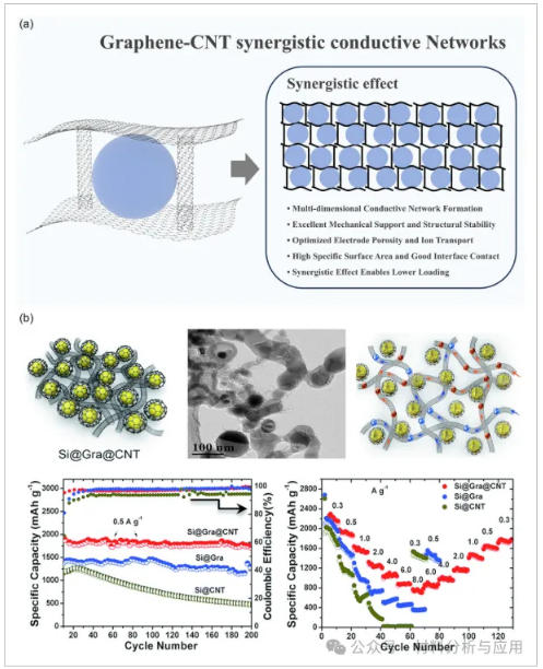
图3、a)石墨烯-碳纳米管协同导电网络及其特征优势。b) 石墨烯-CNT杂化导电网络示意图、TEM表征及相应性能对比。
图4、a) The preparation process and the microscale structure of LFP/graphene composite. b) Comparison of rate capability of LFP/G, LFP/C, and LFP/(G?+?C). c) Comparative cycling performances of LFP/G, LFP/C, and LFP/(G?+?C) operated under 10?C charging and 20?C discharging (Reproduced with permission. Copyright 2011, RSC). d) The synthesis process for the LiFePO4/CNTs nanocomposites. e) The initial charge/discharge curves and rate capabilities of the LiFePO4/CNTs composites electrodes with different C2H4/H2 proportions. f) Rate capabilities and cycling stabilities of LiFePO4 and LiFePO4/CNTs composites at different rates (0.1, 0.2, 0.5, 1, 2, 5, and 10?C). g) Long-term stability of LiFePO4 and LiFePO4/CNTs composites at 1?C. h) Electrochemical impedance plots of LiFePO4 and LiFePO4/CNTs composites from 105 to 0.01?Hz and equivalent circuit. i) Cyclic voltammetry curves of the LiFePO4 and LiFePO4/CNTs composites at a scan rate of 0.2?mV s?1. j) Cyclic voltammetry curves of the LiFePO4/CNTs composites at different scan rates from 0.5 to 3.0?mV?s?1 (Reproduced with permission.[110] Copyright 2025, Elsevier).
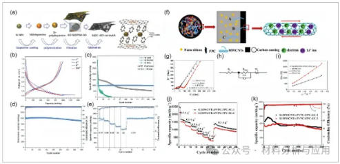
图5、a) The synthetic procedure of the sandwich-structured Si@C-rGO composite. b) Voltage profiles for different cycles. c) Cycling stabilities of Si@C-rGO, Si-rGO, and pristine Si NPs at a current density of 300?mA?g?1. d) Capacity and Coulombic efficiency of Si@C-rGO for 400 cycles. e) Marked charge/discharge capacities at various rates (Reproduced with permission.[138] Copyright 2016, Wiley). f) Schematic illustration of three kind of states of MWCNTs through the SC layer and the transfer behavior of electron and Li ion. g) EIS of Si-MWCNTs-PVPC-FPC-SC-1 and Si-FPC-SC electrode materials. h) Equivalent circuit used to model EIS data for electrode materials. i) Relationship of the Z+re and ω?1/2 of the Si-MWCNTs-PVPC-FPC-SC-1 and Si-FPC-SC. j) Rate capability of Si-MWCNTs-PVPCFPC-SC-1 and Si-MWCNTs-PVPC-FPC-SC-2. k) Long-term cycling performance of Si-MWCNTs-PVPC-FPC-SC-1 and Si-MWCNTs-PVPC-FPC-SC-2 electrode at 1?A?g?1
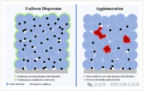
图6、导电剂均匀分散与团聚的示意图。
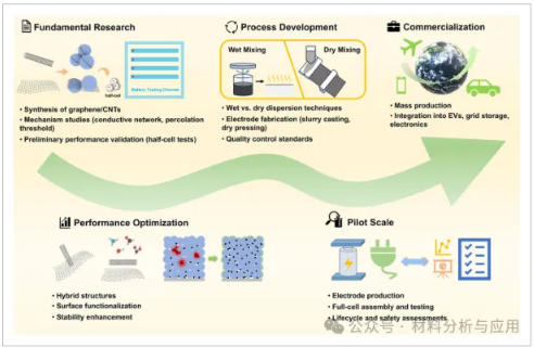
图7、The evolutionary path of graphene and CNT conductive agents from research to commercial implementation.
文献: